Tuesday, May 28, 2013

Finished and waiting for launching.

Tuanella 3 is awaiting transport to Deacon's boatyard on the Hamble River (off Southampton Water) and thence launching. This will require a crane with slings, initially to fit the rudder and keel pod and thence to lower her into the water. I shall have some sacks of aggregate at hand to use for trim if need be and these might stack beneath the floor boards.


The stern light seen below had to be offset to accommodate the excursion of the rudder (not shown on her polypropylene pintles) when going to starboard.


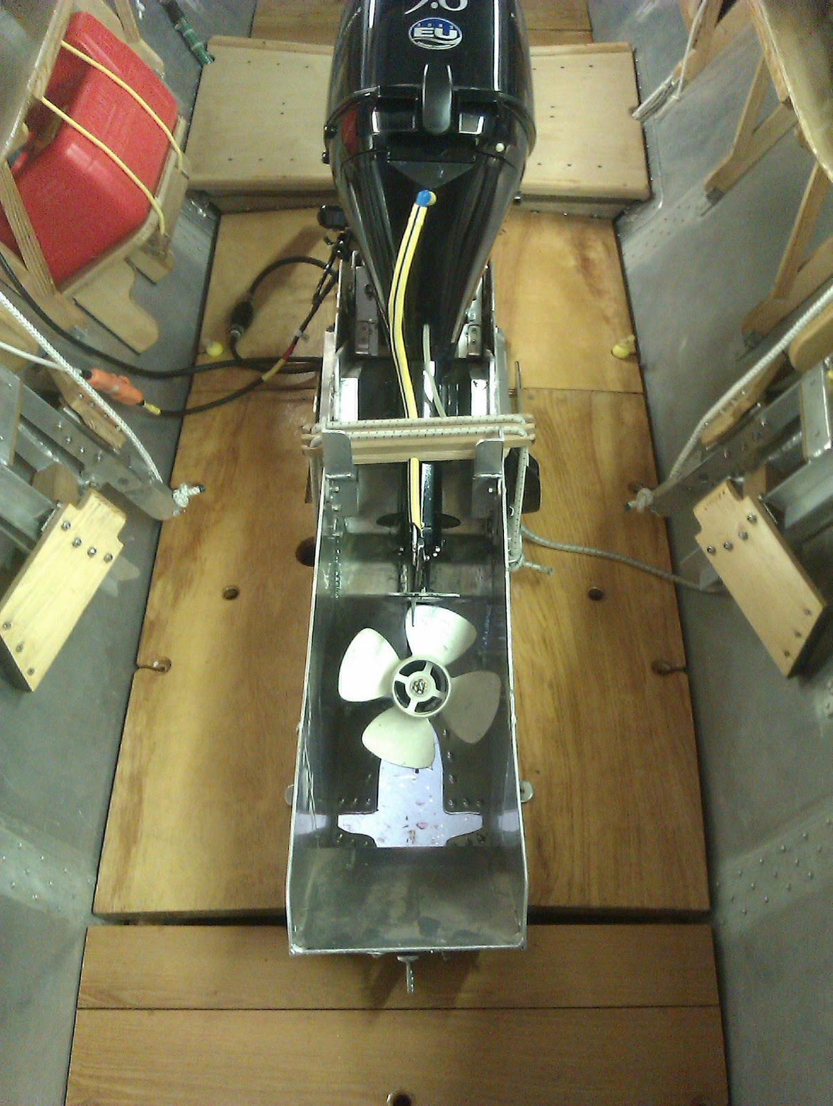
The engine, when raised for 'sailing', overhauling, or transport of the boat, is held secure in its 
box by a wooden bar which is held in place athwartship by stout shock cord, (seen as two white cords) around a sheave portside and back across into a cleat on starboard.


The pitch of the engine in this up position is not so 'flat' that oil can work its way from the gearbox into the head of the engine yet lends itself to easy working access and hopefully good drainage of seawater from the engine and the potential to screw a hose fitting to the base of the engine casting to rinse it through with fresh water. 
Also, some 'muffs' I bought to embrace the seawater inlets on each side of the propeller housing to run the engine out of water using a hose and fresh water, couldn't be fitted on the engine while in gear. I therefore modified them using timber and keeping the original rubber cusps and hose fitting. I think I shall have enough clearance on each side to flush the engine while she lies as shown above. In the picture below the hose connection can be seen just to the right of the yellow bobble.
The wood chock is separating the jaws to demonstrate the rubber cusps that cover the water inlets in the propeller housing. 
The advertising video shows the very muffs that I cannibalized to make what you see below, as the offset of those muffs was insufficient for them to sit tight on the inlets.


Sunday, May 12, 2013

'Anti-foul Language' - so to speak!

Anti-fouling paints depend on biocides in their make-up to inhibit growth of weed and barnacles and are usually hard or self-effacing. In the case of anti-fouling aluminium hulls it is important that the biocidal component, once tin and now copper, doesn't act electrolytically.
    As best I know some copper containing anti-fouling can be use on aluminium but breaks in the undercoats, if untreated, can initiate focal electrolysis.

Another slant at preventing or inhibiting growth on the hull is manipulating the surface such that adherence is impossible, difficult or tenuous when and where motion of the boat through the water is enough to swish or brush growth away. An exciting product, if it works that is, decreasing toxic material in the worlds oceans. Of course one has to think ahead and take count of processes in its manufacture and eventual degradation.

Hempel paints have made a new product called SilicOne for that very purpose, being a three component item, the application of which needs to be somewhat disciplined. It is this I have used on Tuanella 3. The items, a epoxy-resin base, a tie coat (ocre) and the business coat (coloured - in my case, red) come in relatively small size cans (750ml) to avoid waste because the pot life is short (an hour). Understandably the applications need to be quite close together  to allow next coat adherence before drying, and as much as possible each coat covering the entire surface in one. Not always easy this because of the hull supports, so the margins of those areas have a paint free cuffs of each coat that are picked up when the supports are shifted.
Hempel state that the boat should be launched within a month of application of the final coat for best results.

Brush or roller, that is the question. Doing both I found the roller best, as the moment from the axis of the roller surface to its handle is considerably greater than that from the brush drawing action from surface to wrist in the case of a brush and the axle of the roller is relatively friction free. Also the volume of paint 'held' per dip is greater.

I  found with the narrow short haired roller (1") I used held the roller tight on the surface. Patently for nooks, crannies and welds a smallish (1") touch up brush is indispensable.

The finished surface is shiny, rubbery and clammy to the touch, I suspect altogether quite uninviting for the barnacle larvae to attach and how they do so on whales is remarkable.
Paradoxically the surface feels and acts anti-slip as the picture indicates.


As best I recall there are two colours to chose from and I chose red over black, being in my mind the easiest to see if the boat is turns turtle. The picture below shows the colour well.


Saturday, May 4, 2013

A New Hull Form For Catamarans

Peter Richwell suggested that I should register the idea of using my hull design for catamarans, hoping that such attributes as are derived from testing it as a mono-hull will shine when two are joined across.

The profound rise in the use of catamaran construction for commercial and military vessels is a reflection of the design's general ability to improve or solve some the limiting aspects of mono-hulls by way of speed, stability, space, and draft. Costs compared to mono-hull construction, however are greater - after all there are two hulls. However it must be said that such hulls for sailing catamarans do not need the keel, keel section and bottom strength as would a sailing mono-hull and here at least there would be some savings. Indeed the method I have used to build the hull from effectively a single sheet, even denying in a way the actual existence of a keel might mean a great a considerable saving in time and material. Contentious of course are the hull configurations in relation to symmetry and spacing. Allowing for such contention and that the 'mono' hull I have built is for ergonomic benefit, it might be construed that two such symmetrical hulls will offer the same benefits when made into a catamaran. This has been shown not to be always the case and the degree of spacing between them also can markedly effect performance. However in defence of my expectations one might reflect on that the intense crowding, almost 'sardines in a tin' like confinement, of fish being hustled by prey would suggest that there may even be some survival (speed)advantages of being close.( web ref.S.P.E.E.D. Hull design). It seems that proximity of birds flying in certain formnations, especially over long distances like ducks and geese, works to conserve energy. The essential shape of all birds in flight is, teardrop - blunt end forward - the same applies to fish.

 Depending on speed the bottom of the bow should effect some planing, and with the relatively shallow and thin trailing underwater section, the resistance should be low. I expect the boat I have built, calculating from knowing her weight and from the observed displacement of the model to be a light displacement boat. Overall at 18 feet her expectant waterline length is 15 feet. However if she behaves in the manner of a displacement hull 5.2 knots max is all that one might expect, and allowing she is being powered by a modest 9.8 hp outboard, and that her trials will not necessarily be in ideal water and weather conditions, this figure could be knocked down further. Also how much of an encumbrance the stabilising pod will have is yet another thing of concern; it is designed tear drop shaped in the vertical plane to reduce forward resistance but is flat when viewed laterally to increase side-ways resistance and therefore stability against rocking
 Therefore much rests on her trial and a speed of 6 knots or more will be quiet a revelation.