Monday, July 15, 2013

Tuanella III - Quo Vadis?

Things look rather grim for T3. Exceptionally tender, under-ballasted, poor trim, and an engine well that might let in lots of water when these are corrected. Seemingly a dreadful waste of time, energy and money. To start with I built a model which went slipped through the water like a seal but in extrapolating up to the present project  made some real errors in calculating her ballasting. Determining stability and tenderness never crossed my mind partly because as well as the still waters of ponds around London I took the model to the rougher waters on the River Hamble where again, when pushed, or towed, she slid as effortlessly through the chop as the mirror smooth ponds, thus impressing me with her stability. Of course the model was very well ballasted indeed.

 The weight she had on board was for her 31inches (79cms) length was 13.75lb (6.25kg). The weight of the model's steel shell was 6.05 lb (2.75 kg). an all up weight of 19.8 lbs (9kg). At these weights she sat in the water just over half way to the gunwales amidships and slightly less aft.
In extrapolating those weights to T3's length, some 7 times that of the model, I think the weight hike will need to be like that of the volume hike ie the cube of that ratio or 1/7 scale.
The cube of 7 is 343 so if this idea is correct that would mean T3's all up weight should be 6791.4 lb (3087kg) or 3 tonnes.
If that calculation is to be believed and as her actual all-up weight, engine, cabin, lead filled keel pod and accoutrements was 1155lbs (525 kg), one imperial ton or half a tonne, it is small wonder that her footprint on the water was that of an 18' canoe.

Back when I was playing with the model I rang the test tank people at Southampton and they quoted some runs there and calcs against established data for some £2500 pounds.
That seemed a lot. I thought for that much I could knock up a 'life size' model I could actually test with me in it and in many way this, in material terms, was not that wide of the mark.
What was wide of the mark was the other big costs - time - I was working part-time as an obesity adviser - and rent and rates of the space I had here in London to do it - this by far the biggest killer financially.

Using Xray film with its wangy or elastic spring steel quality very much like that of the marine aluminium sheeting of the definitive boat, I played around with various cuts into rectangles of it to produce nice shapes letting the cut surfaces slide over each other.

Having played around with xray film I moved on to using thin gauge steel.


The pattern was simply this: the length of the sheet is twice the width - it can be whatever you like - it's what I chose as it seemed to work out on xray film - the cuts in the bow end (the blunt end) allow the sheeting to slide over itself  to a point such that the bow profile from the side was 45degress, a concession to internal space and an appropriate attitude to oncoming water.
 Since the sheet is truly rectangular it is easy to be bilaterally very accurate in one's markings. The excess of the overlap that lies above the gunwale is trimmed off forward in the line of it aft. This produces a cusp or hollow at the top of the bow which is conveniently filled with a symetrical bi-ellipse to form a supra-prow. For geometrical reasons I never tried to fathom the top of this ellipse is a splendid starting point for decking of the model again forming along the length decking which is at right angles to the gunwhale side along the whole length. Thus the forward decking runs upwards quite markedly and and progressing aft become less so and eventually flat.

The working model was made from a single sheet of thin steel in a few hours.

Naturally I feel flat at the moment and feel I want to be shot of it all. But I have to look back at what I wanted when I started out and that was:
1. to determine that which is not intuitive being whether the tear drop profile so ever present in nature is useful in boat design and
2. whether origami like simplicity in metal bending can offer a easy-build yaght embracing this non-intuitive concept.
I read somewhere that the ultimate in boat design is one that leaves no wake - allowing that a wake represents wasted energy no one would disagree with that though the parameters of performance need defining. Yet in evolutionary terms the tell-tale nature of a wake giving the game away either for the prey or the predator-hunter would be an action packed situation and would suggest the reverse tear drop shape is also meant for speed. Of course how this speed will be affected by the shape will be a function of the fluid's viscosity, which should be low, and its density, which should be high, so as to allow the pressure head developed to be usefully, and that means quickly, redistributed in the post head section of the form to 'squidge' it forward and thus retrieve the initial energy expended.
A bath of mercury might be an ideal liquid satisfying these criteria if one's model was heavy enough not to be displaced onto the surface!
 To stand by a pond and watch a large koi near the surface give a single swish of its tail and no more than this to shoot it forward with not an iota of visible disturbance is exhilarating.
One might think that I should have been building a submarine but the physical mores apply to any fluid, liquid or gas and one would think therefore to an body that is part immersed. The immediate responder might be the termoil at the liquid/gas, water/air interface  would be better negotiated by a sharp leading edge - well this remains to be seen.
One of the outstanding features I found when testing the model is incomparably better directional stability when the craft was pushed - no great shakes of course when the motion comes from pulling - though - when towing any conventional craft through the water the tendency for it to rapidly drift from the line of pull is well known.
Perhaps mentioned earlier, the buoyancy of my craft being well forward will prevent or lessen the likelihood of it being a pitch poled from a following sea by this acting on the wider and larger surface and much more buoyant forward section. Also the fine entry of the stern and its lesser buoyancy must offer an easier helm to control.

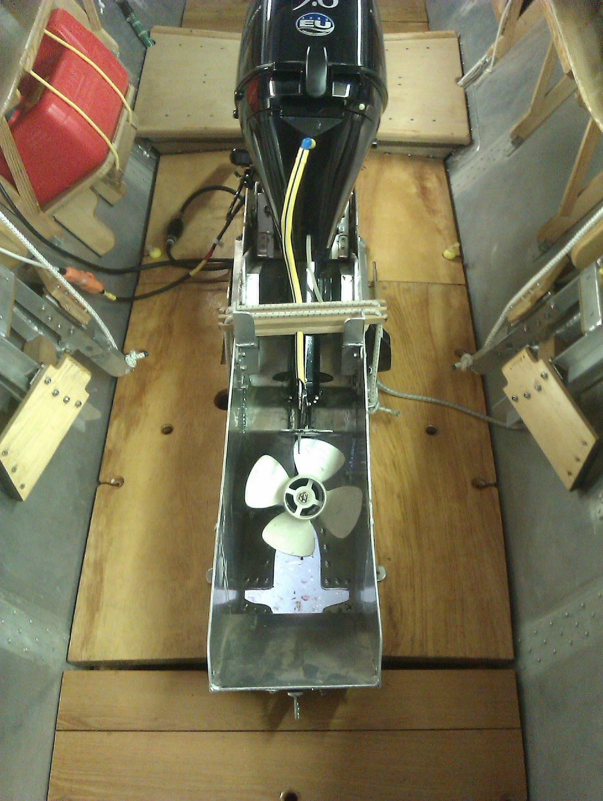
Well here I| am with a 'too floaty boaty'. What to do? Well, one positive need is re-ballasting and one positive outcome from that will be to bring the water level in the engine well dangerously close to filling her with water from the inside. So, the engine and its well will have to go. That can be done quickly. The well can be removed completely or cut just above its junction with the hull thereby offering some purchase for future bracketing etc. Of course the central hole that provided the entry point for the propeller drive will have to be plated unless option* below is taken.
 Then what are my other options for propulsion for the craft? They have to be compatible with adding lots more ballast.
- put an inboard engine in and run a shaft aft and provide a propeller in a cutaway section just forward of the rudder.
- think about an electric motor/battery/generator set up inside the boat.
- attach an electric long shaft engine alongside(outside) aft and accept a bias whilst under power.
-* using the existing hole in the bottom of the hull for a long vertical well to accommodate a very long shaft electric 'outboard'.


Sunday, July 14, 2013

Events Since Launching

   It could be seen a mile off that T3 was sitting too high and well above the waterline marked by the anti-fouling.Her profile on the water was about that of an 18' canoe and that, not unreasonably, pretty much spoke for her stability.


Her being tail up as well was contrary as one of my worries before launching was what I considered to be her fine entry aft would mean my weight at the helm would cause her to go tail down - thus the effort to afford her balance by way of the trim tabs on the rudder and make the sections hollow where possible.


Below shows the hollow rudder tube where the dotted line represents a heavy gauge but thin tube inserting below into a wider tube which houses the rods which locate on the back of the tabs.
The balancing part of the rudder is hollow so as to afford a lifting component to the stern of the boat.


T3 really does lie high in the water - I had calculated she would be down to about an inch below the paint line.


Despite some 176 lbs of bagged aggregate as aft as possible and as low as possible (down under the floor boards)  very little changed by way her footprint on the water. What did happen however was   to level her fore and aft trim. 
In order to test the engine and the mechanism for lifting and lowering it through the hull the boat had to be steadied. A beam clamped across the cabin uprights extended enough across the pontoon to be clamped a bracket held on the pontoon by a sack of aggregate.
......show picture ...............................
The motor started easily and its exhaust girgled merily up from it's propellor hub vents into the engine box in the stationary boat with some 6 inches to go before water would lap into the boat.
This looks bad as the substantial more ballasting required will offer precious little leeway before water would start to tumble in and sink her.
.........show picture of water in engine box and video of engine running ........................................

T3 has been lifted out of the water and dropped into her 8 castor cradle. Pretty much all over the submerge metal work the anti-fouling had bubbled. The blisters show that the separation has occurred between the tie coat and the epoxy- resin. The implications are several. The epoxy- resin was not roughened enough; the epoxy-resin I used was not that recommended by the makers of the anti-fouling; the time from application of the anti-fouling to the boat being launched had to within the month and I think this might have been borderline. Some parts of the submersed pintels that were free of anti-fouling were well covered in green stringy weed - the anti-fouled areas, bubbles and blisters as well, were slightly grubby but essentially without growth - so that was something!


Sunday, June 30, 2013

Tuanella III hits the water

Wednesday 26th June
At Deacons boat yard at the Bursildon Bridge on the River Hamble. Scheduled mast and boat lifts, work with a generally defined time, understandably took precedence and our lift, with issues relating to fitting the keel pod, loading that with lead ballast and hanging the rudder was left to the latter part of the day. Video clips of this, http://bit.ly/10sDocF , show this and her lowering into the water.
The good news is she appeared absolutely water-tight. The less than good news is her trim show her tail up a little and somewhat seriously shy of ballast. The workhorse boat of the yard is seen pushing her across to a work berth. Getting into her to tidy up and set the cover proved her to be worryingly tender. Towards the end of the clips is one showing my friend Ray, with little more than his hand on the cabin, getting her to rock easily.
In a certain vernacular one has to go back to the drawing board, certainly at least to the model, from which it is obvious I didn't extrapolate all, or least accurately information that was there for the taking.
When I tested the model I think a big glitch was determining the ballast.
I used the cube of the  length to scale up the cubic capacity ( 1: 7 ). Allowing that the ballast is a function of cubic capacity and that the weight of ballast that the model needs here................, in my bathtub this morning, for acceptable trim is ........., the cube of this is ..................

A Drascombe lugger near by in the yard and of the same length was some 2.5 the weight of Tuanella.
While she was stationed on the wharf I put 40 kg of bagged shingle aft as possible, and this settled her tail a couple of inches.
I think the position of the pod on the lubber line is too far forward. Changing this is something of a
structural challenge because the housing is an almost inviolate.
What comes to mind which could be possible is to use the support bars of the pod to hold an accessory pod or bar which goes aft.
Another worry, a miscalculation, is the amount of water that rises in the engine box. I thought it would be well down at a level with the lower runners but as she bounces around the level gets quite close, 3-4" from the top.


Monday, June 10, 2013

Tuanella III 'hits the road' - leaving London for the Hamble River.

Sunday morning, on the only weekday one could reasonably expect to go against the one way traffic in the alley onto which the workshop fronts, and, even more importantly a day, on which there were no bus lane restrictions allowing that lane free to load without breaking the law.
    It went smoothly out of the shed, down the alley, onto the awaiting trailer, down the M3 and onto Deacon's boat yard where she now sits on her trolley under a marquee on smooth hard standing.


The 'hitting the road' was uneventful and she now lies in a marquee at Bursledon Bridge on the Hamble River

Tuesday, May 28, 2013

Finished and waiting for launching.

Tuanella 3 is awaiting transport to Deacon's boatyard on the Hamble River (off Southampton Water) and thence launching. This will require a crane with slings, initially to fit the rudder and keel pod and thence to lower her into the water. I shall have some sacks of aggregate at hand to use for trim if need be and these might stack beneath the floor boards.


The stern light seen below had to be offset to accommodate the excursion of the rudder (not shown on her polypropylene pintles) when going to starboard.


The engine, when raised for 'sailing', overhauling, or transport of the boat, is held secure in its 
box by a wooden bar which is held in place athwartship by stout shock cord, (seen as two white cords) around a sheave portside and back across into a cleat on starboard.


The pitch of the engine in this up position is not so 'flat' that oil can work its way from the gearbox into the head of the engine yet lends itself to easy working access and hopefully good drainage of seawater from the engine and the potential to screw a hose fitting to the base of the engine casting to rinse it through with fresh water. 
Also, some 'muffs' I bought to embrace the seawater inlets on each side of the propeller housing to run the engine out of water using a hose and fresh water, couldn't be fitted on the engine while in gear. I therefore modified them using timber and keeping the original rubber cusps and hose fitting. I think I shall have enough clearance on each side to flush the engine while she lies as shown above. In the picture below the hose connection can be seen just to the right of the yellow bobble.
The wood chock is separating the jaws to demonstrate the rubber cusps that cover the water inlets in the propeller housing. 
The advertising video shows the very muffs that I cannibalized to make what you see below, as the offset of those muffs was insufficient for them to sit tight on the inlets.


Sunday, May 12, 2013

'Anti-foul Language' - so to speak!

Anti-fouling paints depend on biocides in their make-up to inhibit growth of weed and barnacles and are usually hard or self-effacing. In the case of anti-fouling aluminium hulls it is important that the biocidal component, once tin and now copper, doesn't act electrolytically.
    As best I know some copper containing anti-fouling can be use on aluminium but breaks in the undercoats, if untreated, can initiate focal electrolysis.

Another slant at preventing or inhibiting growth on the hull is manipulating the surface such that adherence is impossible, difficult or tenuous when and where motion of the boat through the water is enough to swish or brush growth away. An exciting product, if it works that is, decreasing toxic material in the worlds oceans. Of course one has to think ahead and take count of processes in its manufacture and eventual degradation.

Hempel paints have made a new product called SilicOne for that very purpose, being a three component item, the application of which needs to be somewhat disciplined. It is this I have used on Tuanella 3. The items, a epoxy-resin base, a tie coat (ocre) and the business coat (coloured - in my case, red) come in relatively small size cans (750ml) to avoid waste because the pot life is short (an hour). Understandably the applications need to be quite close together  to allow next coat adherence before drying, and as much as possible each coat covering the entire surface in one. Not always easy this because of the hull supports, so the margins of those areas have a paint free cuffs of each coat that are picked up when the supports are shifted.
Hempel state that the boat should be launched within a month of application of the final coat for best results.

Brush or roller, that is the question. Doing both I found the roller best, as the moment from the axis of the roller surface to its handle is considerably greater than that from the brush drawing action from surface to wrist in the case of a brush and the axle of the roller is relatively friction free. Also the volume of paint 'held' per dip is greater.

I  found with the narrow short haired roller (1") I used held the roller tight on the surface. Patently for nooks, crannies and welds a smallish (1") touch up brush is indispensable.

The finished surface is shiny, rubbery and clammy to the touch, I suspect altogether quite uninviting for the barnacle larvae to attach and how they do so on whales is remarkable.
Paradoxically the surface feels and acts anti-slip as the picture indicates.


As best I recall there are two colours to chose from and I chose red over black, being in my mind the easiest to see if the boat is turns turtle. The picture below shows the colour well.


Saturday, May 4, 2013

A New Hull Form For Catamarans

Peter Richwell suggested that I should register the idea of using my hull design for catamarans, hoping that such attributes as are derived from testing it as a mono-hull will shine when two are joined across.

The profound rise in the use of catamaran construction for commercial and military vessels is a reflection of the design's general ability to improve or solve some the limiting aspects of mono-hulls by way of speed, stability, space, and draft. Costs compared to mono-hull construction, however are greater - after all there are two hulls. However it must be said that such hulls for sailing catamarans do not need the keel, keel section and bottom strength as would a sailing mono-hull and here at least there would be some savings. Indeed the method I have used to build the hull from effectively a single sheet, even denying in a way the actual existence of a keel might mean a great a considerable saving in time and material. Contentious of course are the hull configurations in relation to symmetry and spacing. Allowing for such contention and that the 'mono' hull I have built is for ergonomic benefit, it might be construed that two such symmetrical hulls will offer the same benefits when made into a catamaran. This has been shown not to be always the case and the degree of spacing between them also can markedly effect performance. However in defence of my expectations one might reflect on that the intense crowding, almost 'sardines in a tin' like confinement, of fish being hustled by prey would suggest that there may even be some survival (speed)advantages of being close.( web ref.S.P.E.E.D. Hull design). It seems that proximity of birds flying in certain formnations, especially over long distances like ducks and geese, works to conserve energy. The essential shape of all birds in flight is, teardrop - blunt end forward - the same applies to fish.

 Depending on speed the bottom of the bow should effect some planing, and with the relatively shallow and thin trailing underwater section, the resistance should be low. I expect the boat I have built, calculating from knowing her weight and from the observed displacement of the model to be a light displacement boat. Overall at 18 feet her expectant waterline length is 15 feet. However if she behaves in the manner of a displacement hull 5.2 knots max is all that one might expect, and allowing she is being powered by a modest 9.8 hp outboard, and that her trials will not necessarily be in ideal water and weather conditions, this figure could be knocked down further. Also how much of an encumbrance the stabilising pod will have is yet another thing of concern; it is designed tear drop shaped in the vertical plane to reduce forward resistance but is flat when viewed laterally to increase side-ways resistance and therefore stability against rocking
 Therefore much rests on her trial and a speed of 6 knots or more will be quiet a revelation.

Saturday, April 6, 2013

Modifications to the Engine

http://www.youtube.com/my_videos_timedtext?video_referrer=watch&video_id=UPanT5LTK6E&feature=mhsn

An Explanation of the Engine Compartment

The power for the boat is from a Tohatsu long shaft 9.8 hp four stroke outboard. The decision to avoid an outboard placement of the engine is that the pointed stern really doesn't lend itself to this, having no transom nor stern post for it to be fixed to. Also any extra weight astern will have the tendency to sink the fine and less buoyant stern and change the attitude of the boat to the waterline. However, to choose an outboard motor to be placed inboard might seem a little bizarre but compactness, ease of removal and maintenance and freedom from portals broaching the hull seemed to make sense at least and in the nature of an experimental boat this itself seemed a worthwhile project. Another advantage could have been, had I been prepared to make a considerably larger hole in the bottom of the boat, to allow full excursion of the steering capacity of the engine as happens normally with the engine on a transom, rotating as it does on a vertical placed high the general housing of the engine. Considering the present placement of the engine at 2/3rds the boat length this would have had a remarkable effect on its steering capability acting as though there was an angled component of a bow thruster. Anyway the small exit for the propeller hub and shaft precluded this but it is an interesting item for the future.

Sunday, March 31, 2013

Video of New Natural Boat Design


This is one of my first videos of Tuanella 3, the new natural tear drop boat design.

Saturday, March 9, 2013

Electrics, Getting Ready For Launching and Insurance Issues

Structurally, the boat is finished. She has a couple of coats of epoxy resin below the water line and over the internal seams along the rivet lines and is now ready for Silic One, patently a silicone based paint that is described, not as anti-fouling but fouling release, pressing home its mode of action relying on surface tension and anti-adherence properties. It has no biocides to pollute the water. The point of having a non-metal containing products relates to me seeing many dismal reviews on the net about those copper containing ones which have caused problems on aluminium boats in the nature of electrolytic action when the undercoat has been breached, which must be pretty common on small craft.

I say 'she' for her name is Tuanella 3. I bought my first yaght brand new and had to find a name that for the Southampton Ship Register that hadn't been allocated. Not the easiest I found but the word Tuanella came to mind out of the blue, one not already registered and, checking as best I could, rationalised Tuan, being Malay for master and also old Australian for flying fox, with the 'ella' component as a feminisation of both meanings to give mistress or female flying fox. Either meaning seemed ok; however much later a sailing colleague pointed out that Tuanella was the name of the realm of the dead in Finnish and Estonian folk lore. Somewhat dismayed at this information I checked the spelling and it was quite different being Tuonela, so I relaxed and left things as they were. Tuanella and Tuanella 2 both were marvellously care-free and on which my then partner and I spent thousands of enjoyable hours. The new name is emblazoned  across her prow and the tail end of her gunwales, port and starboard, in the biggest letters that would fit.


The navigation lights, starboard and port, were easy to install but the stern light was awkward, the boat's sharp aft design precluding any transom and therefore  needed a special bracket to clear the excursion of the rudder and tiller and be astern enough for the close angle of the light to be visible from both sides aft.


The battery for these, a typical leisure one of 12 volts, 60 amp hrs and weighing 16 kg sat low and forward to the starboard side of the keel housing. Allowing that a serious leek or problem could occur around the keel housing all the fixing of the battery is arranged for rapid removal to provide immediate hull inspection. Even the connections to battery terminals are of the quick release type.
The battery platform is held in place by an easy and quick release wooden chock that holds it hard against the bottom of the boat and the aluminium cross bar of the keel housing.


Also the battery itself can be installed or released quickly through the wooden batten that straddles the two bulwarks.


The 'outboard' engine has an alternator and a leash of wires emerge from it to charge a battery. Not of massive output (12v, 6amp, 80 W) but allowing this particular engine was designed for small sailing craft it is almost certainly enough. As the engine is, from a position of action down through the hull or 'lifted' for sailing, mooring or repair, there needs to be plenty of  length of the aforementioned leash to accommodate this change of position. This leash has a commodious connection by plug to the battery circuit.
The connection to the battery, somewhat free-floating to accommodate various positions of the engine, is that designed for an electric lawn mower and whose female pegs are well shrouded.


                                    When not in use it clips neatly under a nearby seat


The engine, a Tohatsu 9.8 hp long shaft four strokes, has a rectified output to charge a battery,
12 volts, 6 amps, 80 watts, which comes out on a plastic covered leash of some 60cms. To the end of this the male complement  was fixed - it too being exceptionally well shrouded, importantly of course as the pins could easily short by touching the aluminium hull.


The boat has been built in an arch underneath a railway line and getting the boat from there to an adjoining alley-way and thence to a public road for loading, has necessitated building a trolley around her which hopefully will aid in running her up on a transporter, trolley and all. The trolley will be useful in moving her around the boat yard when she reaches there. It has been made in square formation using scaffolding boards; cheap, cheerfull and strong - their rough finish provides good grip when they are bolted to each other. The bogies, two on each corner, one of each pair with a foot brake, are quite hefty being of the type to support large catering facilities.


Interestingly certain things come to light when building a novel boat, not the least being surveying and insurance, the former being necessary before the latter can occur. In the UK such boats cannot be sold before five years have lapsed after launching, presumably to generate appropriate sea-worthy provenance.
Also the question of insurance becomes awkward as such a lack of provenance makes underwriters quite wary. A bit of a Catch 22 situation develops -  the underwriters want a surveyor's certificate but and a he, in this case, won't give one till he sees her in the water. Anyhow the underwriters have covered her third party till a formal survey and valuation have been submitted which at least lets me get her into the water.
Another thing the insurance insisted on was installing an automatic sump pump and for this I chose the Whale Supersub Smart 650, http://www.whalepumps.com/marine/home.aspx, the automatic electrics relate to a 'field switch' which turns on when water covers it, but by virtue of a delay component does not turn on from the effect of trivial slop in the bilge. It also allows a switch to override this automatic component.
The unit is compact and bright yellow and the way its been installed, I can remove it quicky to allow access if  an emergency arises by way of a serious leak from the keel housing on the hull.


Here the pump can be seen sitting in the floor board housing in an aluminium 'recess' and is locked in place by a hinged strut that comes across its body and is pinned by a quick release bungee.


The makers stress the importance of not having anything touching the 'field end', here where the wires are seen emerging and the picture below, where the pump is in situ in the bottom of the boat, clearly there is good space all around the 'field' element.


Cabin lights - these would have in the past been hard wired but with 'led' technology and the ensuing battery and life expectancy of the bulbs I chose to install them in tapered aluminium sockets,one under the foredeck and one in the cabin. Ease of removal means they can double up as a torch.


The electrics, not quite complete are centred around the battery and the keel housing. Naturally one tried to keep them, or rather any wettable terminal or junctions boxes as high as possible. However one such junction can be seen, positioned for convenience in the wooden runner, at the proposed waterline. The switch gear, is held high below the seating.


Here the keel housing, the electric runs, the battery and the automatic pump are covered by boards,  creating a step in the general line of the floor boarding.


The boat, along its bottom, is absolutely flat, with not a jot of sheer to offer some central sump effect to any water taken in, so there will be a tendency for such water to slop from one end to the other whence in motion. For this I have installed a hand pum at each with the strum box at the forehead end fixed hard against the hull. The pump arrangement aft is much the same but the strum box is free from any fixture, the gutter here being narrow enough to keep it where it's meant to be.

The petrol tank is held convenient to the engine on a small platform under nearby seating and held there by two quick release bungees. In the matter of balancing being well to port, it somewhat offsets the weight of the much heavier battery which is to starboard but much more central.